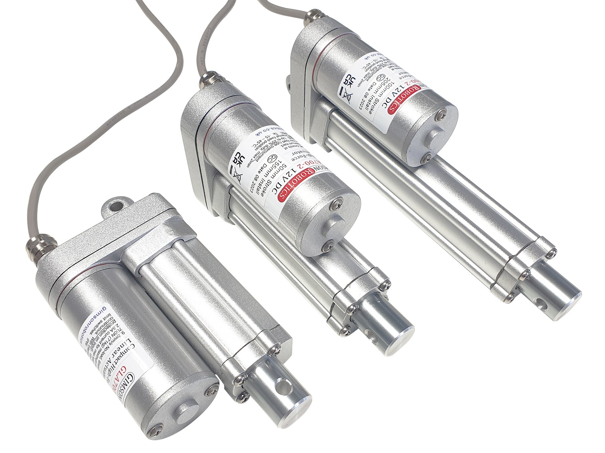

GLA700-2 12V DC Compact High Force Linear Actuator

The GLA700-2 is a small-sized linear actuator with a high build quality and useful load capacity of up to 700N (71kg). The actuator has a no-load running speed of 9.2mm/s and a full-load speed of 6mm/s.
This model is currently stocked in six different stroke lengths (travel distances) of 30mm, 50mm, 100mm, 150mm, 200mm and 300mm.
This design offers improvements over our older GLA750 actuator model, including a more-stylish body construction and higher quality seals around the body.
Please see below for more product details.
Availability: IN STOCK
SKU: GLA700-2-12-30
Couldn't load pickup availability
GLA700-2 (230AGR Version)
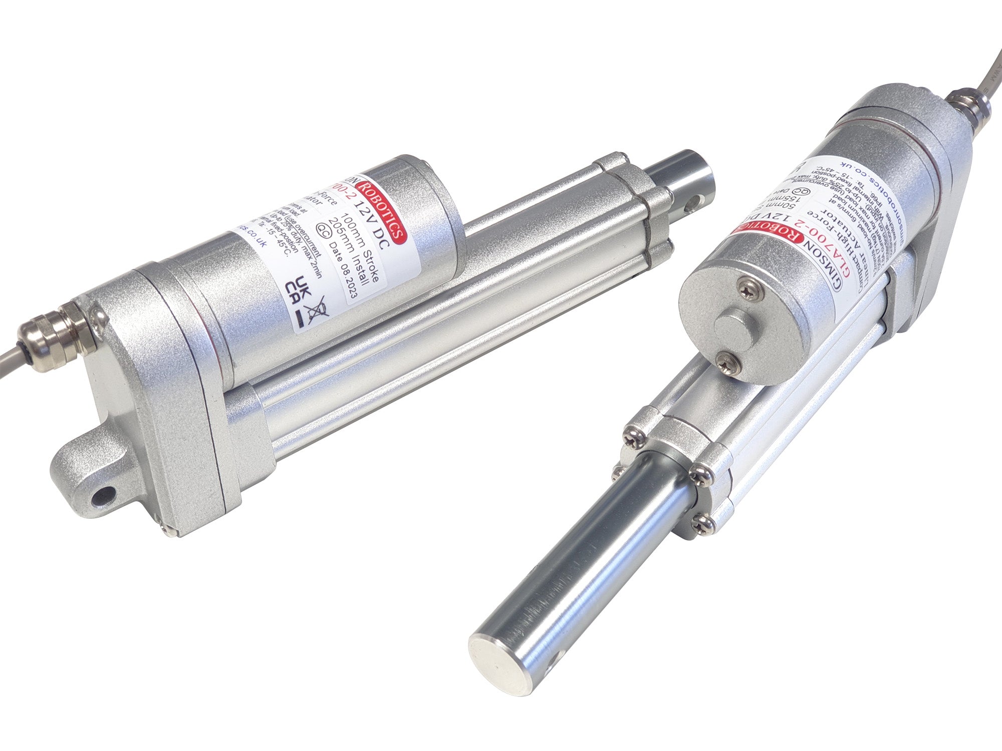
The GLA700-2 offers the build quality of higher-cost actuators at an affordable price, with a small body size ideal for providing electrical automation in tight spaces. The operating voltage of 12V DC makes it suitable for powering from a standard lead-acid battery, or running from a mains to 12V DC adapter.
The shallow lead-angle of this actuator (with a 3.175mm pitch, single-start screw) means that if the actuator is driven into a position it will tend to stay in that position unless power is applied once again, or unless it is subjected to a load larger than the rated load.
The outer enclosure features O-ring seals under every external screw head as well as gaskets at each seam and a sturdy wiper ring about the extending rod. This design adds up to an IP66 enclosure rating, suitable for most external use. Bear in mind that the actuator should not be submerged in water, or exposed to continuous running water. If mounting outdoors it is best to orient the extending rod tilted downwards, so that water tends to run away from the moving seal between rod and body.
Please be aware that, with its all-metal spur gear transmission, this actuator model is not intended to be especially low-noise by design. If your design requires low-noise actuators please ask us for advice on other alternatives.
The actuator is supplied with a 0.8m PVC insulated lead as standard (black external sleeve with two internal cores), with bare tinned lead ends. Please contact us if you require a customised lead or connector option.
User Advice
 Device Safety
Electric actuators such as this model are low-voltage electromechanical components that are used in a wide variety of different applications. It is important that the safety of each installation is assessed according to its own requirements, construction, end user and environment. Be sure that you have checked suitability, including any fail safes appropriate to your application, before use.

A PDF copy of the actuator datasheet can be downloaded here.
Operating Characteristics

Maximum load: 2.8A. If using overcurrent detection to protect the motor, ensure that this is sensitive enough to react quickly to an overcurrent event.
< 58dB under full-load
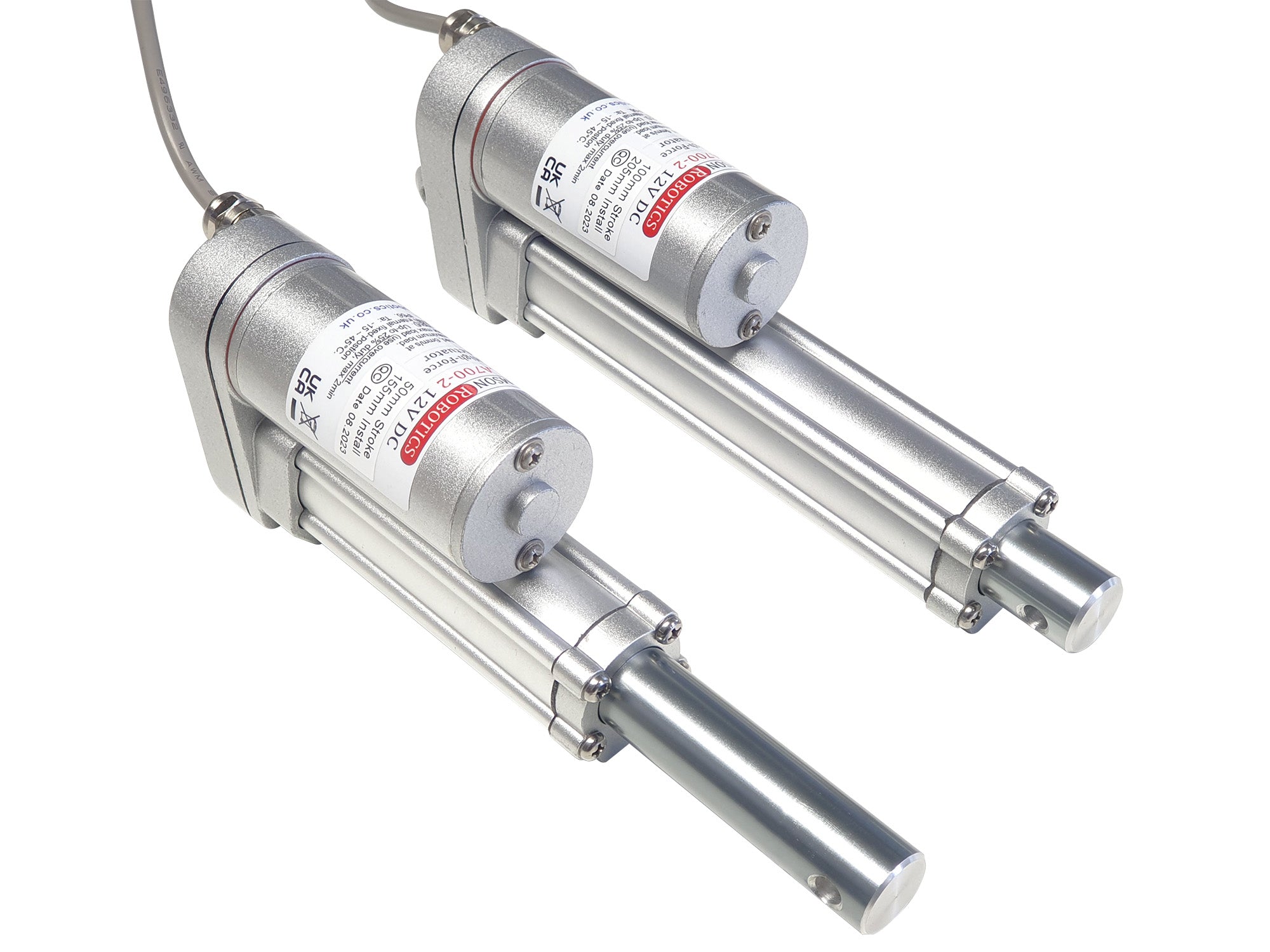
Actuator Build Detail
(click on image to expand)

| 30mm stroke: 135mm | 50mm stroke: 155mm |
| 100mm stroke: 205mm | 150mm stroke: 255mm |
| 200mm stroke: 305mm | 300mm stroke: 420mm |

Due to these components being in series with the actuator motor, you should ensure that either control is only with DC currents (not via PWM), or that you have tested for compatibility with your controller and operating cycle.
| 30mm stroke: 730g | 50mm stroke: 760g |
| 100mm stroke: 840g | 150mm stroke: 920g |
| 200mm stroke: 990g | 300mm stroke: 1170g |
If you have any questions about this item, including requests for bulk-pricing information, then please contact us.
Related Products
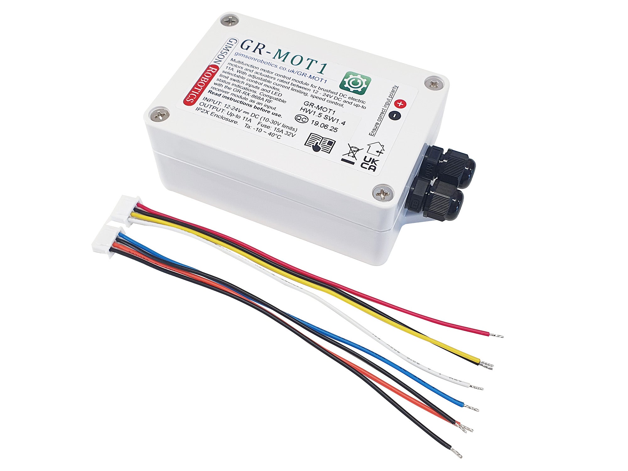
GR-MOT1 General Purpose Motor Control Module (12-24V DC)
from £59.80 £69.77 inc VAT
A highly adaptable motor controller for DC electric actuators, with adjustable overcurrent responses, speed control, and optional remote control operation, all mounted in a convenient plastic enclosure.
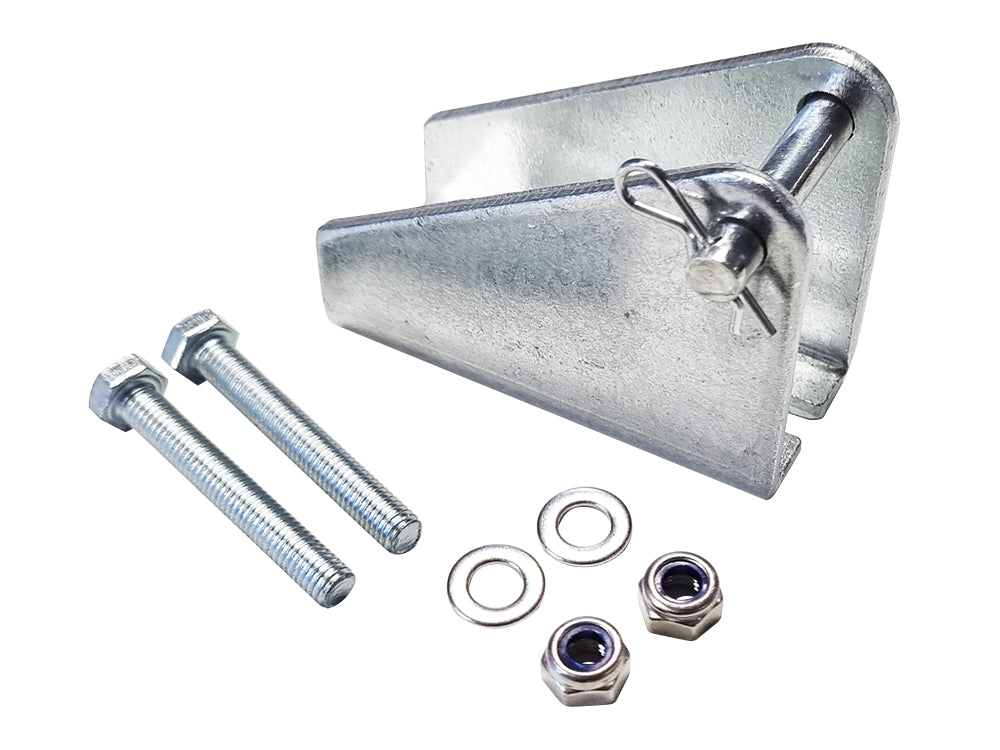
Small Steel Actuator Mounting Bracket, 6mm
from £5.50 £6.42 inc VAT
Steel brackets for mounting the GLA700-2 or similarly sized linear actuators with a 6mm mounting pin onto control surfaces
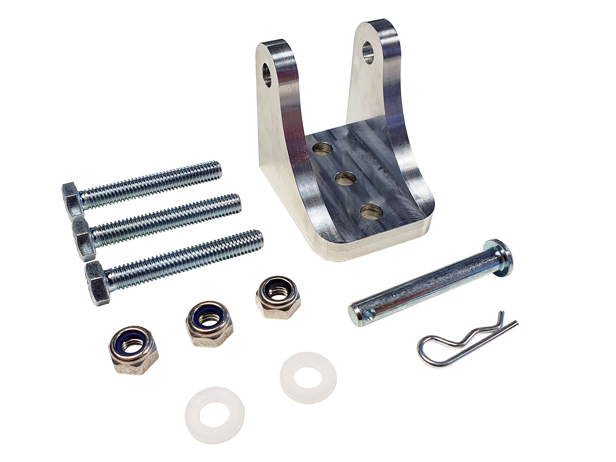
Machined Aluminium Linear Actuator Mounting Bracket, 6mm
from £8.40 £9.80 inc VAT
6061 aircraft grade aluminium brackets for mounting actuators with a 6mm mounting pin. Complete with mounting accessories
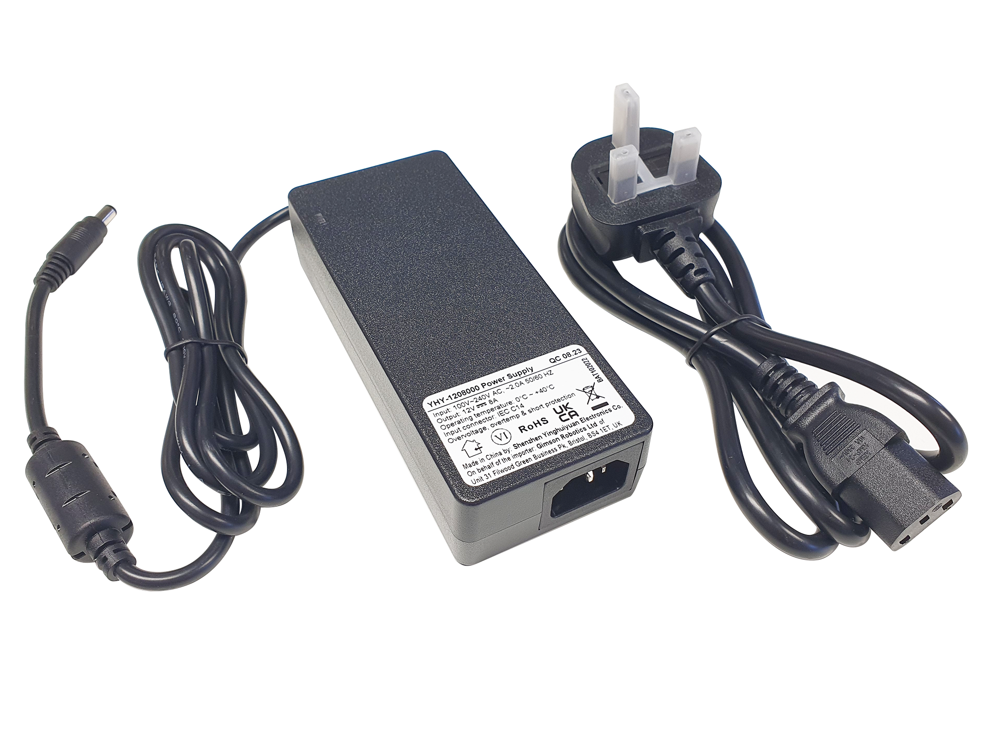
AC to 12V DC 8A Power Supply/Adapter for Motors & Actuators YHY
£24.60 £28.70 inc VAT
A compact and high-efficiency power adapter, specially designed for use with DC electric motors and actuators