


GR-MOT1-V2 General Purpose Motor Control Module (12-24V DC)
The GR-MOT1-V2 is a highly adaptable motor control module exclusive to Gimson Robotics. The device allows brushed DC motor and actuator loads of between 12 - 24V DC, and of up-to 11A, to be controlled via wired switch inputs (external low-current switches), and/or via an optional RF receiver module (with the addition of part reference GR-RX-868A2, leading to the combined reference GR-MOT1-V2-RX).
The controller features adjustable directional current limiting (different limiting values may be set for each control direction D1 and D2), speed control, selectable control modes (momentary or latching, for both wired and remote inputs), limit switch inputs, control status indications (LED indication of various controller states), voltage and temperature protections. This second-generation iteration of the device, V2, adds further hardware and software fault protections, and improves the controller efficiency, reducing idle current draw and allowing for longer-duration outputs.
Every controller is supplied mounted in an enclosure along with 3x M10 cable glands, 1x M10 hole plug, and 1x 4-way wired connector for the optional connection of external limit switches (with Blue, Black, Orange, Black wires).
Availability: IN STOCK
SKU: GR-MOT1-V2
Couldn't load pickup availability

The GR-MOT1-V2 is the second-generation version of our popular GR-MOT1 motor control module, redesigned from the ground up with several years of experience built into the hardware and firmware. It allows for the reliable control of connected motors and actuators, with soft-start and fast-response current limiting helping to ensure system longevity.
Features at a glance
Built-in protection
What's new in V2
Compared with the original GR-MOT1, the V2 hardware and firmware add many fault protections and improve driver efficiency, cutting idle current draw and allowing for longer-duration loaded outputs before the controller overheats. Here's a summary of properties, with key changes shown:
| GR-MOT1-V2 | GR-MOT1 | |
|---|---|---|
| Supply limits | 9–32V | 10–30V |
| Enclosure | IP54 with M10 cable glands | Not sealed, not IP tested |
| Wired controls | Screw terminals, via side cable gland | 4-wire connector lead |
| Input HIGH level | 2–12V | 3.3–12V |
| Idle current (no receiver) | 2.9–3.6mA in sleep mode | <9mA |
| Status LED | Green, red and blue states | Red only |
| Overcurrent sensitivity | 50ms or 150ms | 60ms or 120ms |
| 20A fast cut-off | After <10ms | After 20ms |
| Overtemperature | ~70–80°C, plus a secondary cut-off at ~80–90°C | Cut-off at ~75°C |
Also new in V2: Reverse-polarity protection, short-circuit detection, hardware self-tests, a start-up lock-out and an automatic low-power sleep mode.
Connecting it up

Power connects to GND and VCC (12-24V DC nominal, 9-32V limits).
It is recommended to have overcurrent protection (e.g. a fuse) at the power source itself (e.g. at a battery) to protect against shorts on the power leads themselves. It is also normally useful to have an accessible way of disconnecting it, either a connector or a switch.
Your brushed motor or actuator connects to MA and MB. Connections here can be in either direction: swapping the two wires to a DC motor inverts which direction D1 and D2 each drive.
Power and motor terminals take 0.5–2.5mm² conductors (strip 7mm, tighten to 0.5Nm). Use between 3 to 6mm OD round cable through the end glands, so that they can grip the cables effectively.
For wired control, connect switches between the 3V3 terminal and the D1, D2 or STOP inputs on the control terminal block. The inputs are active HIGH (2-12V), so an external positive control signal can be used instead of a switch.


Using only one limit switch? Keep the other pair of pins (e.g. L2 and GND) connected together.
Control terminals take 0.1–1.3mm² conductors (strip 4-5mm, tighten to 0.2Nm). Use 3-6mm OD round cable through the side gland, so that it can grip the cable effectively.
Settings and adjustment
Everything is set on the board, with no software or programming needed. Tap a heading below for the details, and always test operation carefully after changing a setting.

- 1.Wired control terminals
D1, STOP, D2 and 3V3 - 2.Status LED
Green, red and blue indications - 3.Remote receiver header
For the optional GR-RX-868A2 - 4.DIP switches
Control modes, trip time, auto-reverse - 5.Current limit dials P1 and P2
Separate limits for D1 and D2 - 6.Speed dial P3
Maximum output speed, 20–100% - 7.Limit switch inputs
L1 and L2, bridged as supplied - 8.On-board fuse
15A ATO blade fuse - 9.Deceleration link
Hard braking (M1) or soft stop (M2)
Current limits and overcurrent response Dials P1 and P2, trip sensitivity, auto-reverse and the 20A cut-off
The controller monitors output current to protect your load, your power supply and itself. Dial P1 sets the limit for the D1 direction and P2 for D2, each from 1 to 11A (default ~6A in the 12 o'clock position). Setting them separately means you can protect asymmetric loads, such as an assembly lifted against gravity, where more current is needed to raise than to lower.
Allow ±15% between a dial's marked position and the actual setting.

If the current stays above the set limit for longer than the trip time, the output hard-stops (motor braking). DIP switch SW3 sets that time: 50ms (default, high sensitivity) or 150ms. After a trip, the status LED pulses red once a second until you give an opposite-direction command or a STOP input.
With auto-reverse enabled (SW4 ON), the output drives the other way for 2 seconds after a P1/P2 trip, without an operator command, so keep clear of the load. Any input, or STOP, cancels the reverse.
Separately, a fixed 20A fast cut-off stops the output if the current exceeds 20A for >10ms, for example on a short circuit or a severe stall. Movement is then blocked for 10 seconds, shown by a repeating triple red blink.


Speed control Dial P3, or an external potentiometer or control voltage
Dial P3 sets the maximum output speed (PWM duty, switched at ~19.6kHz) from 20% to 100%, with a default of 100%. As a guide, on a 24V supply with speed set to 50%, most DC motors run as they would on a 12V supply. Every movement starts with an 800ms soft acceleration, which reduces the start-up current spike and the mechanical shock on your system.

Advanced users only: to use an external potentiometer or control voltage, remove the resistor labelled EN (this disables P3) and connect to the board pads V, S and G (3V3, speed signal and ground). S at 3.3V gives 100% speed and S at 0V gives 20%.
Control modes (DIP switches) Momentary or latching, trip sensitivity, auto-reverse

| Switch | OFF (default) | ON |
|---|---|---|
| SW1
Wired inputs |
Momentary: runs only while D1 or D2 is held | Latching: press once to start, press either direction (or STOP) to stop |
| SW2
Remote inputs |
Momentary | Latching |
| SW3
Overcurrent trip time |
50ms (high sensitivity) | 150ms (lower sensitivity) |
| SW4
Auto-reverse |
Off | Reverses for 2 seconds after a P1/P2 trip |
Wired and remote modes are set independently. Each switch change is confirmed by two red blinks, and if the output is running when a change registers, it stops.
Stopping: hard brake or soft deceleration Blue link on M1 (default) or M2

By default (M1) the controller brakes the motor at the end of each movement by shorting MA and MB together, giving a rapid stop. Moving the blue link to M2 gives a softer 500ms deceleration ramp for regular movements, while STOP still acts immediately.
The M2 deceleration ramp is regenerative. Only select it if your power supply can handle regenerative current.
Status LED guide What each colour and blink pattern means
Each strip reads left to right over time.

Power off

Idle, awake

Idle, in low-power mode awaiting input

Output on (output current active)

STOP active, or auto-reverse underway

Limit switch open, preventing movement

Low-current drop-out (no load detected, output turned off), OR confirmation of a DIP switch state change

Over 20A (fast surge overcurrent trip)

Overtemperature: Wait for the controller to cool

Overcurrent trip (P1 or P2 limit exceeded)

Under or overvoltage error

Hardware fault. Remove and reapply power; if it returns, stop using the device and contact us with the blink count (or solid on).
Protection features in detail Voltage, temperature, polarity, drop-out, self-tests and fault recovery
Voltage. The output hard-stops if the supply goes above 32V or below 9V, or if it rises by more than 20% for over 100ms during a movement (including deceleration). That rise check protects power sources that can't absorb regenerative current. If it trips while braking, check the deceleration link is on M1, and if that doesn't help, consider a different power supply. The output is re-enabled 10 seconds after the supply returns to range.

Temperature. The output stops at roughly 70–80°C, measured on the board beside the output transistors, and resumes automatically once cooled, with no power cycle needed. An independent hardware cut-off acts at roughly 80–90°C. Both are well below the ratings of the fitted components.
Reverse polarity. The controller is protected against reverse connection of the DC supply and won't operate until it is corrected.
Low-current drop-out. Many actuators have built-in limit switches that cut the motor current at the ends of travel. If the output is on but the current stays below ~50mA for over 1 second, the controller assumes the end of travel has been reached (or the load is disconnected) and switches off, with two red blinks. The next movement command re-arms the output. This also helps diagnose an installation where nothing happens.
Hardware self-tests. At power-on, and continuously while running, the controller tests its own drive hardware, including sensor plausibility checks. A detected fault disables the output with a blue LED indication.
Start-up lock-out. The controller won't act on a direction input that is already on. A fresh D1 or D2 input is needed after power-on, after a fault lock-out clears and after any internal reset, which prevents unexpected movement when power is restored.
Fault recovery. After a 20A overcurrent or a voltage error, movement is blocked for 10 seconds and the LED keeps showing the fault for 30 seconds.
On-board fuse. A 15A 32V ATOF automotive blade fuse (Littelfuse 0287015) is fitted as a secondary failsafe. The electronic 20A cut-off acts faster than most fuses, so it is unlikely to blow in normal use. If you replace it, use no more than 20A.
Enclosure and mounting Dimensions, cable entries, IP54 and heat

The controller is supplied mounted in a tough ANC160 flame-retardant ABS enclosure (101 × 69 × 40mm body, 133mm overall length, 2 × Ø3.5mm flange mounting holes at 112mm centres). Cable entries are via the included M10 cable glands: two end-entry positions for the input power and output motor cables, and a side-entry position for wired control. The side position is closed with a blanking plug as supplied, which must stay fitted unless replaced with the included gland.
With glands correctly fitted (tightened onto round multicore cable of 3–6mm diameter), unused entries blanked and the lid secured with its four M4 screws, the installed assembly achieves an IP54 rating. Note that IP54 is not an outdoor rating: for outdoor use, install within a suitably rated outer enclosure.
Mount on a flat, rigid surface in any orientation. Where splashing is possible, point the cable glands downward or sideways so water drains away. A translucent light guide carries the status LED through the side of the enclosure.
The controller has no external heatsink and sheds heat gradually through the enclosure, so it is best suited to intermittent, low-duty operation. Leave clearance for airflow and avoid hot surfaces and direct sunlight. Sustained high-current loads may trigger the automatic overtemperature response.
Optional remote control
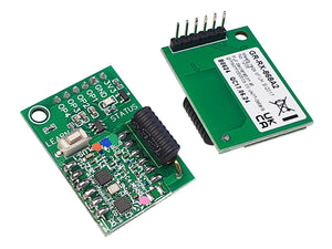
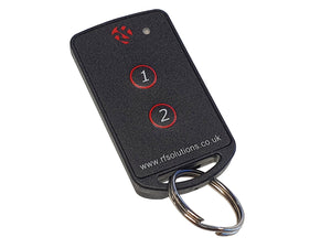
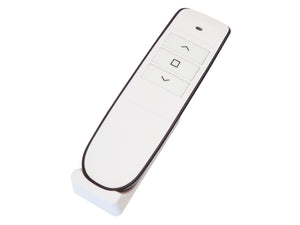
Plug a GR-RX-868A2 receiver module onto the board's 6-pin header (combined part reference GR-MOT1-V2-RX) to operate the controller by 868MHz radio remote. Remote inputs can be momentary or latching (DIP SW2), set independently of the wired inputs, and both can be used together. We recommend that most remotely operated systems also keep wired controls, as a back-up or override.
Wired inputs take priority over remote inputs, except STOP, which has equal priority from either source.

Technical information
| Part ID | Standard model: GR-MOT1-V2. With optional remote module: GR-MOT1-V2-RX |
|---|---|
| Operating voltage | 12–24V DC (limits 9–32V DC) |
| Output | 19.6kHz PWM (20–100% duty), up to 11A maximum (current limits are adjustable) |
| Idle (sleep) current | GR-MOT1-V2: 3.6mA at 12V, 2.9mA at 24V
GR-MOT1-V2-RX: 7.9mA at 12V, 5.9mA at 24V |
| Wired input logic | D1, D2, STOP: active HIGH (ON) 2–12V, LOW (OFF) 0–0.8V |
| Accelerations | 800ms acceleration; 0ms deceleration (regen off), or 500ms with regen deceleration enabled |
| Temperature ratings | Ambient −10°C to 40°C. On-board overtemperature protection. |
| Supply protections | Overcurrent protection (>20A fast-response cut-off), 15A on-board fuse, undervoltage <9V, overvoltage >32V |
| Enclosure | 101 × 69 × 40mm body, 133mm overall length. Mounting: 2 × Ø3.5mm holes at 112mm centres. Material: ANC160 ABS (flame-retardant). |
| IP rating | IP54. The installed rating depends on the cable used and correct use of the cable glands. |
| Power terminals | 0.5–2.5mm² conductors, 0.5Nm torque, strip 7mm. 3–6mm OD round cable for end glands. |
| Control terminals | 0.1–1.3mm² conductors, 0.2Nm torque, strip 4.5mm. 3–6mm OD round cable for side gland. |
| Supplied with | 3 × M10 cable glands, 1 × M10 hole plug, 1 × 4-way JST-XH limit switch connector |
| Device standards | BS EN IEC 61000-6-1:2019, BS EN IEC 61000-6-3:2021, BS EN IEC 63000:2018. UKCA marked. |
Questions and troubleshooting
1.I press a switch and nothing happens
After power-on or a fault, release and re-apply an input. As a safety measure a fresh input is required to enable the output after a power reset.
2.My actuator stops part-way and the LED pulses red every second
3.I get a voltage error (4 red blinks) and the motor stops
4.Can I control it from a PLC or microcontroller?
5.Does it work with actuators that have built-in limit switches?
6.Can it run an 11A load continuously?
7.Can I use it outdoors?
8.The LED is showing blue
The GR-MOT1-V2 is a general-purpose brushed DC motor controller, supplied as a component for incorporation into other equipment. It has no defined end application and has not been assessed for any. It must not be used where failure or uncommanded movement of the load could cause injury, or as part of any safety function: the STOP and limit switch inputs are control functions, not safety functions. If you incorporate it into your own product, you are responsible for assessing its suitability, for the design and testing of your product, and for compliance with all legislation that applies to it. Supplied subject to our Terms of Sale.
- The output may be powered without a command if a fault occurs. Fit an accessible supply disconnect, and keep clear of the load and its travel during operation and testing.
- Fire risk: never operate without supply-side overcurrent protection. The on-board protections cover the output, not a short on the input supply leads.
- Hot surfaces: components may exceed 80°C in normal loaded use. Disconnect the supply and allow 10 minutes to cool before removing the lid.
- This equipment is not a toy. Keep out of reach of children.
If you're unsure whether this controller suits your application, or have questions about bulk orders or customisation, please contact us.
Related Products
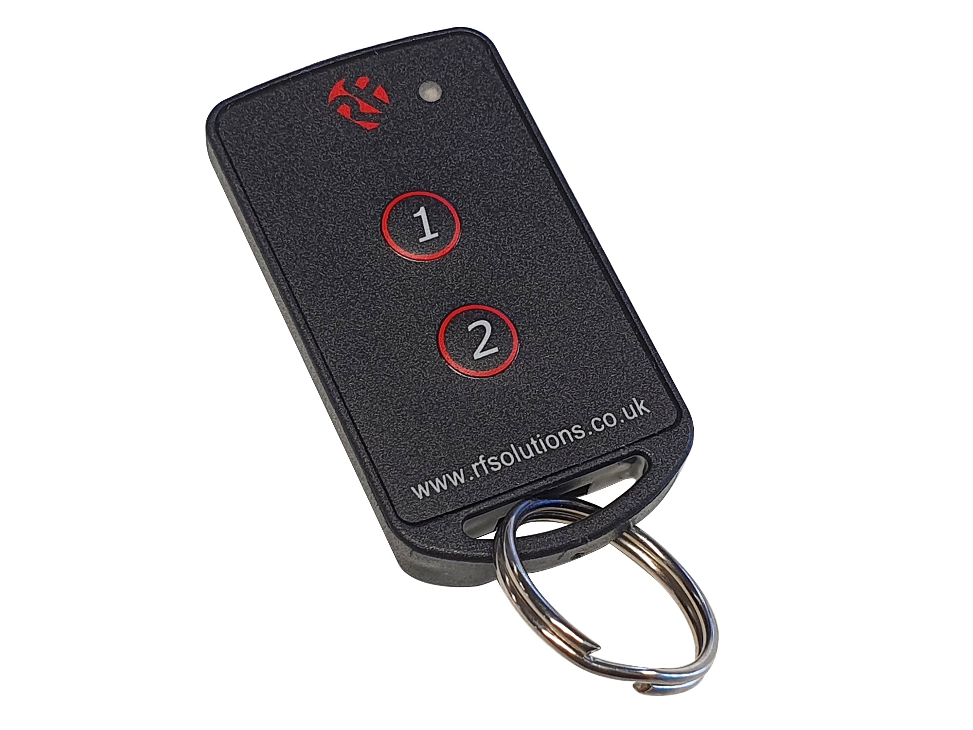
Fobber 2-Channel 868MHz Keychain Remote Control
£19.89 £23.21 inc VAT
A compact keychain mounted 2-button remote control, compatible with the GR-RX-868A receiver module from Gimson Robotics.

GR-MOT1-V2 Customisation: add a Pre-Wired Rocker Switch
from £17.70 £20.65 inc VAT
This is an add-on product for the GR-MOT1-V2 controller. If purchased at the same time as a controller it adds a pre-wired rocker switch to the controller input.

GR-TX-868A2 868MHz Hand-Held Remote Control
£39.80 £46.43 inc VAT
This stylish remote control features three rubberised buttons in a slim black and white body. It is compatible with the GR-RX-868A2 and most RF Solutions 868MHz radio receiver modules.

GR-RX-868A2 868MHz Receiver (ZPT-8RS module interface)
£24.00 £28.00 inc VAT
This receiver assembly adds a compact antenna, learning button and status LED to the ZPT-8RS 868MHz 4-channel module from RF Solutions.