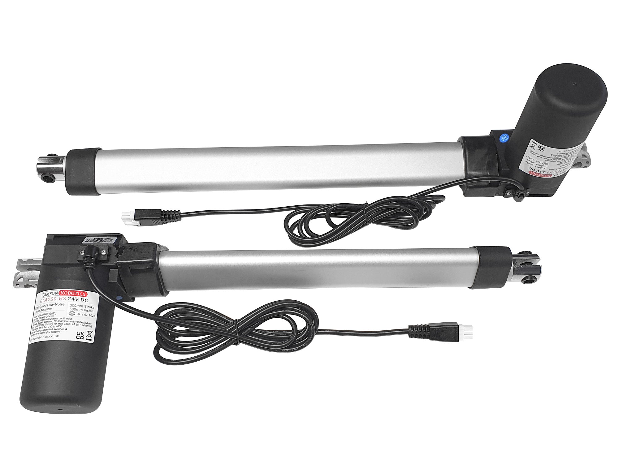
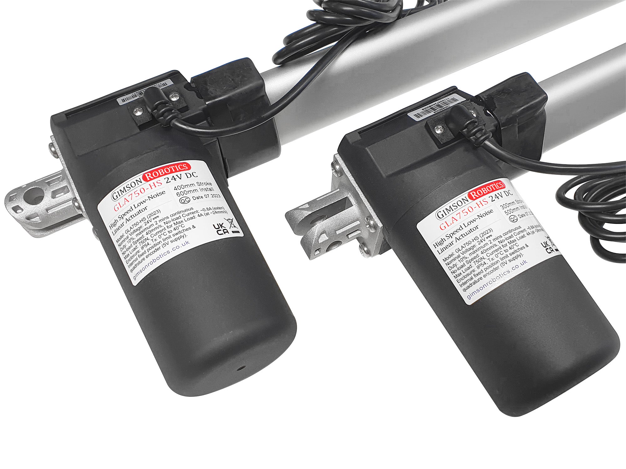
This model of actuator is the fastest-travelling standard model that we offer (faster options are available on a made-to-order basis only). Despite the relatively fast travel speed it is also one of the quietest models that we offer. The GLA750-HS is a very sturdy actuator, combining 10mm bore mounting points, metal end brackets, and a tough (glass fibre reinforced) plastic body.
We stock stainless steel mounting brackets designed specifically for use with this actuator, see the actuator accessories category above.
If you need a greater load capacity, and speed is not so important, please see our related GLA3000-N model.
Integrated Encoder, for position detection and synchronisation
The actuator has a hall-sensor based quadrature encoder built-in to the motor. The encoder is powered by two of the six cores of the main cable (+Vcc Red, -GND Black) and accepts a supply voltage of 5V. It has a dual-channel output (channel A Yellow lead, Channel B Orange lead), with each channel generating 3.46875 pulses per millimetre of travel (3 complete pulses per motor revolution). One of the channels is out of phase with the other, as such it is possible to tell both the speed (from pulse frequency) and direction (by reading the pulses of one channel and comparing it to the other) of the motor. The nature of the signals that are generated is illustrated below. Given a maximum no-load travel rate of 39.2mm/s for the 12V motor (when run at 12V) the maximum pulse frequency would be ~135.975Hz per encoder channel (or the frequency rate may be greater than this if your controller is counting all rising/falling edges as opposed to only HIGH/LOW signal state changes). When used with the appropriate controller the encoder signals can be used for positional control with much greater accuracy and consistency than potentiometer-based actuator feedback systems.

Leads & Connector Options
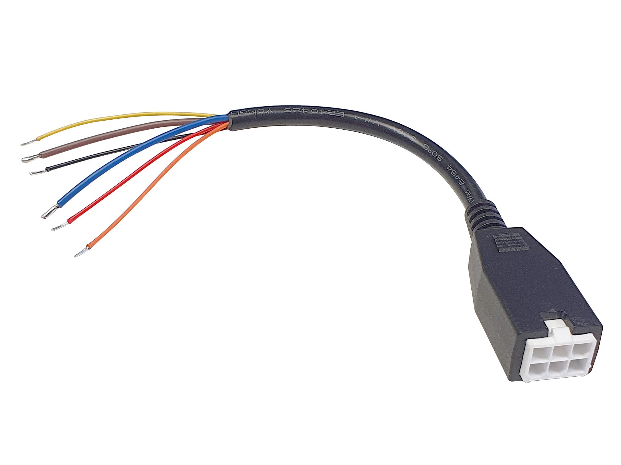
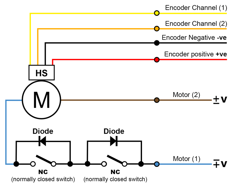
The actuator comes with a 2m long PVC-insulated lead as standard, with a Male 6-pin connector (4.2mm pitch, 3x2 format, latched) on the end (see below for connector image). The cable has six internal cores: Blue and Brown (to the motor, thicker wires), Red and Black (positive and negative power to the hall sensor encoder circuit, thinner wires), Yellow, and Orange (outputs from the encoder, channel 1 and channel 2, also thinner wires). The connections are illustrated in the below diagram which also shows the limit switch circuit inside each actuator, in series with the brown and blue motor leads.
Please see the Electrical product section (link above) for Female 6-pin adapters and extension leads, which are available seperately. If you have a custom lead length or connector requirement, please contact us.
Output Orientation
Both ends of the actuator can be rotated by 90 degrees so that the motor points perpendicular to the two mounting pin axes, which can allow the actuator to fit into tight spaces where the motor would otherwise collide with the surroundings. The below picture shows an example actuator with both brackets rotated. If this change suits your installation you can either request this modification to be made in advance of ordering, or if you are careful it is possible simply using a large cross-head screwdriver (the extending rod-end must only be rotated by 90 degrees anti-clockwise maximum, and the four screws retaining the rear bracket must be replaced securely but not over-tightened).

User Advice
As with any brushed DC electric motor, the direction of travel is affected by the polarity of the current supplied to the two motor wires (see leads & connector description above, and on the
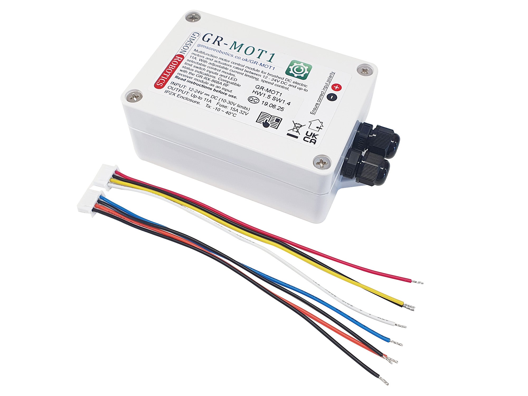
reference sheet, to identify the motor wires). Controlling the direction the current may be achieved using hardware such as our rocker switch harness, or GR-MOT1 control unit. By varying the input voltage between 0-24V DC it is possible to control the speed of the actuator. Reducing the voltage will also reduce load capacity (for example at 12V the actuator will have roughly half of the maximum load capacity as at 24V, and run with roughly half the no-load speed). As with any DC motor the actuator may be run at a higher voltage than the nominal 24V DC however operation at higher voltages
will invalidate the warranty as it creates an increased risk of premature failure.
Shock loads through the mounting points should be avoided (shock/impact loads may impart a force greater than the rated load through the actuator).
Be aware of the 'duty cycle' rating of the actuator, which determines the maximum proportion of the time that the actuator should be in operation for, to prevent overheating and ensure longevity. This is specified under 'Operating Characteristics' below.
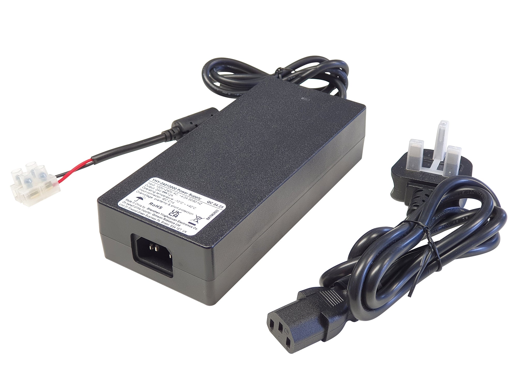
Ensure that the control hardware and power source are capable of providing sufficient current for the loads you expect the actuator to experience. We cannot be held liable for damage caused to connected hardware due to inappropriate hardware selection.
A fuse, and/or other overload protection (such as active current monitoring), should be used to protect the actuator against stalling due to an overload, which can permanently damage the motor.
 Device Safety
Electric actuators such as this model are low-voltage electromechanical components that are used in a wide variety of different applications. It is important that the safety of each installation is assessed according to its own requirements, construction, end user and environment. Please see a list of design principles on page 3 of the
actuator reference sheet (PDF), which we strongly recommend that you adhere to in your end-application design.
CAD models (STEP, IGS, Autodesk Fusion 360) of the actuator are available upon request. Contact us with the size(s) and file formats that you require and we'll attach the files in return.

Operating Characteristics
Motor
24V DC brushed permanent magnet motor, up-to 100W
Speed / Force
40mm/s no-load, reducing to 24mm/s at the full rated 750N

Operating current
No-load: ~0.5A during extension, ~1A during retraction (this difference is normal, due to a feature of the actuator to prevent overrunning the limit switches during the more-common compressive loading)
Maximum load: 4A. Do not apply power to the actuator if the load exceeds the maximum rating, this would void the warranty and be likely to damage the gearbox, bearings or motor. If using overcurrent detection to protect the motor, ensure that this is sensitive enough to react quickly to an overcurrent event.
Maximum load
750N (76kg) for supported (linear) loads.The maximum load should be reduced if the load is not supported in an axial direction, parallel to the movement of the actuator. Longer-travel actuators are affected to a greater extent by off-axis loads.
Maximum static load
750N (76kg). Due to the steep lead-angle of this model (enabling greater travel for each rotation of the screw), in certain conditions it is possible to back-drive it when power is off.
Noise levels
< 48dB under no-load
< 52dB under full-load
Maximum duty cycle
10%. This is the maximum proportion of time that the actuator may be in operation for, up to 2 minutes during any continuous stretch. For example, if operating for 1 minute you should then allow it to rest for 9 minutes before operating again, so as to prevent overheating.
Life expectancy
Nominal 30,000 strokes
Please be aware that there is likely to be some variation in the operating performance from actuator to actuator, allow for at least 10% difference above/below the given values. If you intend to use the actuators in sets of two or more driving the same assembly then you must ensure that the driven assembly is rigid enough to transfer forces between them effectively or else the output could twist and put excessive stress on the framework and actuators. If your structure is not very rigid, or needs to stay level throughout its travel (e.g. tabletop surfaces rising/falling level to the ground) then please get in contact to discuss automatic synchronising control options.
Actuator Build Detail
Size
(click on image to expand)
Installation length
Stroke Length + 200mm. This is the distance from the front to rear mounting hole centres
when the actuator is retracted.
| 100mm stroke: 300mm |
200mm stroke: 400mm |
| 300mm stroke: 500mm |
400mm stroke: 600mm |
500mm stroke: 700mm
| 600mm stroke: 800mm
|
800mm stroke: 1000mm
|
|
Add the
Installation Length to the
Stroke Length to get the full travel distance, as measured between the centre of the two mounting holes.
Mounting
Two 10mm-bore holes. One at the end of the cylindrical piston rod, the other towards the rear of the gearbox housing. Both mounting points feature vertical slots to enable a variety of mounting methods. Both mounting points may be rotated by 90 degrees so that the motor points perpendicularly to where it would otherwise point, which is particularly useful for hatches, furniture and other space-limited installations. Tailor-made mounting brackets are available here.
Body material
Aluminium piston-rod and main sleeve, tough plastic-enclosed motor and gearbox housing. Metal front and rear brackets.
Enclosure rated to IP54, only suitable for outdoor use if protected from running water and high levels of condensation.
Operating temperature
0°C ~ +40°C
Transmission
Single-stage worm-wheel gear reduction (18.5:1 ratio), driving a 4mm pitch 4-start (16mm lead) screw
Limit switches
Two limit switches are installed at the ends of travel which automatically stop travel at the fully retracted and extended positions. The internal circuit is as pictured below (click on image to expand):

Cable
3m long 6-core lead (to connector), with 2 x 0.75mm² cores (Brown and Blue, to motor) plus 4 x 0.25mm² cores (to quadrature encoder), when the standard option is selected
Weight
When supplied with standard lead
| 100mm stroke: 2100g |
200mm stroke: 2400g |
| 300mm stroke: 2650g |
400mm stroke: 2900g |
500mm stroke: 3200g
| 600mm stroke: 3450g
|
800mm stroke: 4100g
|
|
If you have any questions about this item, including requests for bulk-pricing information, then please contact us.




 Device Safety


