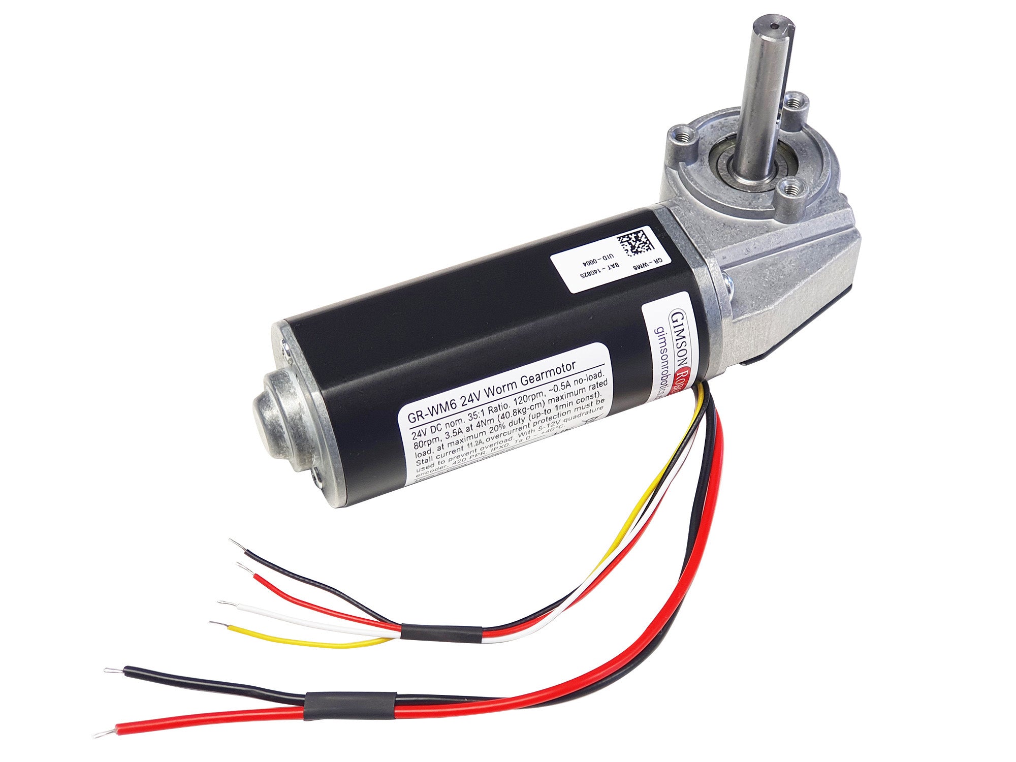


GR-WM6 24V 120rpm Low-Noise Compact Worm Gearmotor
The GR-WM6 is a 24V DC geared motor with a worm-wheel transmission designed for quiet operation whilst providing a decent amount of torque for various automated systems. It runs at ~120rpm unloaded, and at ~80rpm at the maximum rated 4Nm (40.8kg-cm) output torque (this load rating must not be exceeded, to ensure gearbox longevity). The maximum duty cycle, to prevent overheating, is 20% (up-to 1min continuous).
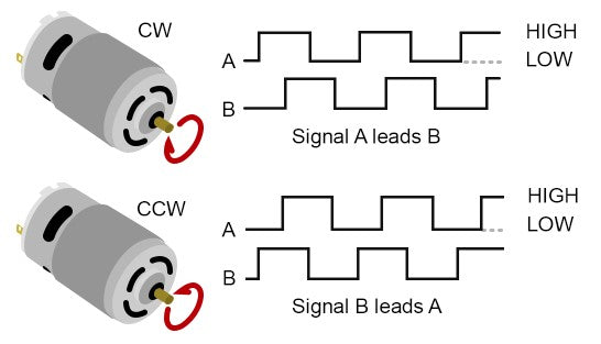
A 12PPR quadrature encoder on the motor allows the output to be tracked accurately (420 pulses per revolution of the output shaft, after the 35:1 ratio gearbox), enabling precise speed or position control and for multiple motors to be synchronised with an appropriate controller, such as the GR-SYNC.
The output shaft is 10mm in diameter, with a 4mm keyway. Please bear in mind that the gearbox is NOT self-locking. Read on below for further details.
Availability: IN STOCK
SKU: GR-WM6
Couldn't load pickup availability
GR-WM6
The motor has been assessed to EMC standards EN 61000-6-3:2021 and EN 61000-6-1:2019, and it is RoHS compliant. Bear in mind that EMC compliance should be re-assessed in end applications as it is dependent upon the connected power & control hardware.
Please consult the product reference sheet for more details.

Integrated Encoder

Cable & Connector Options
User Advice
Motor Dimensions
Please see drawing below. CAD models are available, please contact us for a copy.

Construction Detail
Features a 26mm long, 4mm wide and ~2.2mm deep rectangular keyway.
The gearbox is designed for low-noise operation with a polymer worm-wheel, however this does mean that it is more-sensitive to overheating and also to overloading (especially impact loads) than other gearbox types, as such the maximum duty cycle and load torque ratings must be adhered to strictly, otherwise the gearbox may fail. We recommend using a controller with fast-response current limiting, such as the GR-MOT1 or the GR-SYNC.
Please be aware that it is normal for there to be some variance in performance from motor to motor, it is advisable to allow for a minimum safety factor of 10% above/below the given values when designing for your application. You should also factor in acceleration torque, as this can sometimes be much greater than steady-state load torque, especially if accelerating quickly (for example, with no ramping).
Be sure that any equipment that you use with the motor (power source and controller) is capable of handling the currents that the motor may demand, whilst also being able to limit the current to protect the motor in the event of the load increasing beyond the rated values.
Related Products
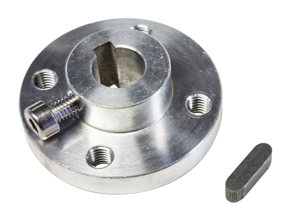
10mm Aluminium Machined Mounting Hub with Keyway
£10.90 £12.72 inc VAT
An easy to use mounting hub with included M4 set-screw and four M5 mounting holes. 10mm Bore
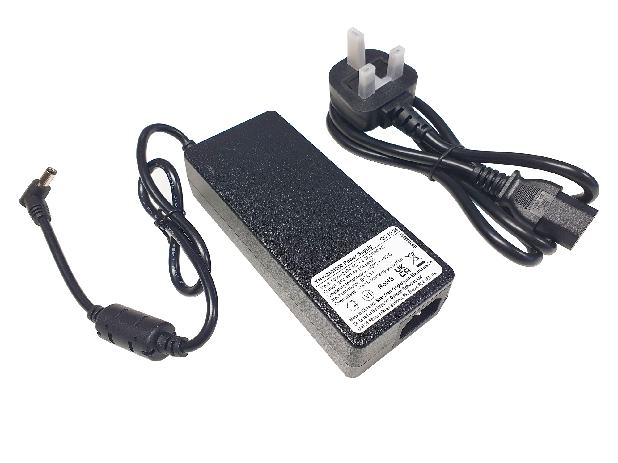
AC to 24V DC 4A Power Supply/Adapter for Motors & Actuators YHY
£24.60 £28.70 inc VAT
Compact 24V high-efficiency power adapter, designed for use with DC electric motors and actuators
GR-SYNC Synchronising Actuator Control Module
£149.00 £173.83 inc VAT
The GR-SYNC is a highly adaptable motor controller, ideal for operating pairs of actuators or electric motors running together. A built-in OLED display provides live status information, and a menu system for control configuration.

6-pin 3x2 Male Connector, 4.2mm Pitch, 1m lead
£3.30 £3.85 inc VAT
An adapter cable, allowing an interface between Female 6-pin connectors (often from motor controllers with an encoder reading feature) and wired terminations