GR-SYNC Synchronising Actuator Control Module
The GR-SYNC is a sophisticated and highly configurable motor controller designed for operating one or two brushed DC electric motors or actuators with encoders. When connecting two motors (of the same model) the controller will synchronise their positions with one-another, ideal for applications where pairs of actuators need to run square with one-another. It can operate both 12V and 24V motor systems.
The positions of connected motors are constantly monitored, allowing the device to automatically slow down and stop the output in pre-configured positions, and also allowing the start and end positions to be digitally edited through the menus. Adjustable directional current limits can allow the controller to detect abnormal loads, stopping the output automatically to avoid damage when configured appropriately.
By integrating an OLED display, the controller provides the many configuration setting menus, and live controller status information, right on the device without any interfacing accessories being required. Via the 6-pin connectors on the controller, many Gimson Robotics actuators such as the GLA3000-N and GLA-Q40 models, can plug straight in without cable modifications.
Read on below for more information.
Availability: IN STOCK
SKU: GR-SYNC-1.2-2.12
Couldn't load pickup availability
The GR-SYNC, an exclusive Gimson Robotics product, aims to simplify the process of adding precise control, and synchronisation, to actuated systems, whilst providing the feedback, and configuration options, to allow it to be used in many different applications. Some of the controller's features are described below, and a summary video is available on YouTube here.
Make sure to read the device instructions before use (a printed copy is included with each controller), which goes into greater detail about the controller and how it can be used.
The frequently asked questions page lists some common questions and their answers, however if you're still unsure of something please contact us.

Key Controller Features
Integrated Display
One of the controller's most powerful features is the integrated OLED display (Black background, White content) and menu buttons. This interface eliminates the need for any external software or programming accessories. All settings — from phase travel speeds and current limits, to Servo Mode and Set Point configurations — are accessible directly on the device. The display also provides invaluable live feedback during operation, with display options including:
- ▶ A live travel bar showing the active output position (between Home and the End Limit), with any active input states (e.g. 'D1 Active') displayed above and underneath (Display Mode 1).
- ▶Live current draw for each motor, perfect for diagnosing load issues (Display Mode 2).
- ▶ The peak current recorded during the last movement cycle, helping you to configure optimal directional current limits for the system (Display Mode 3).
- ▶ The live encoder count(s) for ultimate precision tracking (Display Mode 4).
Compatibility with Many Different Motors and Actuators
The controller is able to interface with many different brushed DC electric motors and actuators, provided that they are rated to between 12V and 24V (limits 9 - 30V), and provided that they each have a quadrature (2 channel) encoder generating a maximum of 2000Hz per channel and able to operate at either 5V or 12V.
We stock many actuators that can be plugged straight into the controller, including the GLA3000-N (12V and 24V versions), GLA750-HS, and GLA-Q40 (250N and 750N versions), whilst for some other actuators and motors, those with 6 wires and a compatible encoder, interfacing can sometimes be as simple as adding a 6-pin Male connector to interface with the connectors on the side of the controller. Example compatible motors without connectors as standard include our GLA800-N and GLA1500-N linear actuators, and our GR-EP-45ENC and GR-WM4-ENC gearmotors.
Complete Motion Profile Control
The GR-SYNC provides fine-grained control over the movement cycle, ensuring smooth, reliable, and repeatable operation. See example motion graphs on page 4 of the instructions.

Smooth Motion: You can adjust the acceleration and deceleration ramp times, preventing jerky starts and stops which reduces mechanical wear in connected motors and transmissions, and minimises electrical current spikes.
Easy Setup: The Homing routine (see page 5 of the instructions) allows the controller to find and record a 'zero' position for one or two actuators. Following this, the End Limit Calibration process lets you run the actuator(s) to your desired end point and save that position with the press of a button (the travel distances can also be adjusted numerically in the menus).
Gentle Stops: You can configure 'slow-down zones' near the travel limits (adjusted via HOM SL and END SL in the Control Settings menu). When an actuator enters these zones, it will automatically reduce speed for a more gentle approach to its final position.
Advanced Control Modes for Complex Automation
Beyond simple back-and-forth movement, the GR-SYNC unlocks advanced control possibilities via Set Point Mode and Servo Mode (see page 6 of the instructions for more details).
1. Set Point Mode: Allows you to define up-to three intermediate adjustable stopping positions between the Home and End Limit. These positions can be triggered by external hardware inputs, commanding the controller to automatically travel to a specific point and stop. To ensure a smooth arrival, the controller will decelerate to a slower speed (SLO SPD) as it approaches the set point target position (with the slower-travel distance being adjusted with SP SLO).
2. Servo Mode: Transforms the controller into an intelligent positioning system. In this mode, a DC voltage signal between 0V and 4.5V on the IN1 input corresponds to a target position along the actuator's full range of travel. This is ideal for creating systems that respond to a variable input, such as a control dial/lever (potentiometer/rheostat), or a command signal from a microcontroller like an Arduino.

Device & Output Protective Measures
To ensure robust and safe operation, the controller is equipped with multiple layers of protection:
Directional Current Limits
Set independent current limits for each travel direction to handle asymmetrical loads and to automatically stop (or auto-reverse) if an unusual load is detected. Fine-tune sensitivity with settings like CUR SEN (overcurrent sensitivity) and CUR RT2 for ultimate protection.
Over/Under-Voltage Detection
Set custom voltage thresholds (MIN VLT & MAX VLT) to automatically stop the output and help prevent damage due to excessive drain on a supply, or due to excessive charge being sent back to the supply (through regenerative braking). The hardware also includes built-in TVS surge protection.
Overtemperature Detection
On-board sensors constantly monitor the device temperature, automatically disabling the motor outputs (with an error indication on the display) if they get too hot and re-enabling them once a safe temperature is reached.
Duty Cycle Tracking
The controller can help to protect connected motors from excessive use/overheating by using the average current monitoring settings (DTY 3, DTY 10, & DTY 30, in the Advanced menu) to ensure they operate within their rated duty cycle limits.
Encoder Error Detection
In dual-channel mode, the controller can detect if one motor stalls or stops unexpectedly and halt the second motor to prevent mechanical damage to your assembly. This is affected by the setting ENC T/O, encoder timeout, in the Control Settings menu.
Device Self-Testing
The controller's software regularly runs integrity checks on its processor and memory to ensure that the control loop is stable and that all stored configuration settings remain uncorrupted.
Related Products

GR-RX-868A2 868MHz Receiver (ZPT-8RS module interface)
£24.00 £28.00 inc VAT
This receiver assembly adds a compact antenna, learning button and status LED to the ZPT-8RS 868MHz 4-channel module from RF Solutions.

6-pin 3x2 Male Connector, 4.2mm Pitch, 1m lead
£3.30 £3.85 inc VAT
An adapter cable, allowing an interface between Female 6-pin connectors (often from motor controllers with an encoder reading feature) and wired terminations
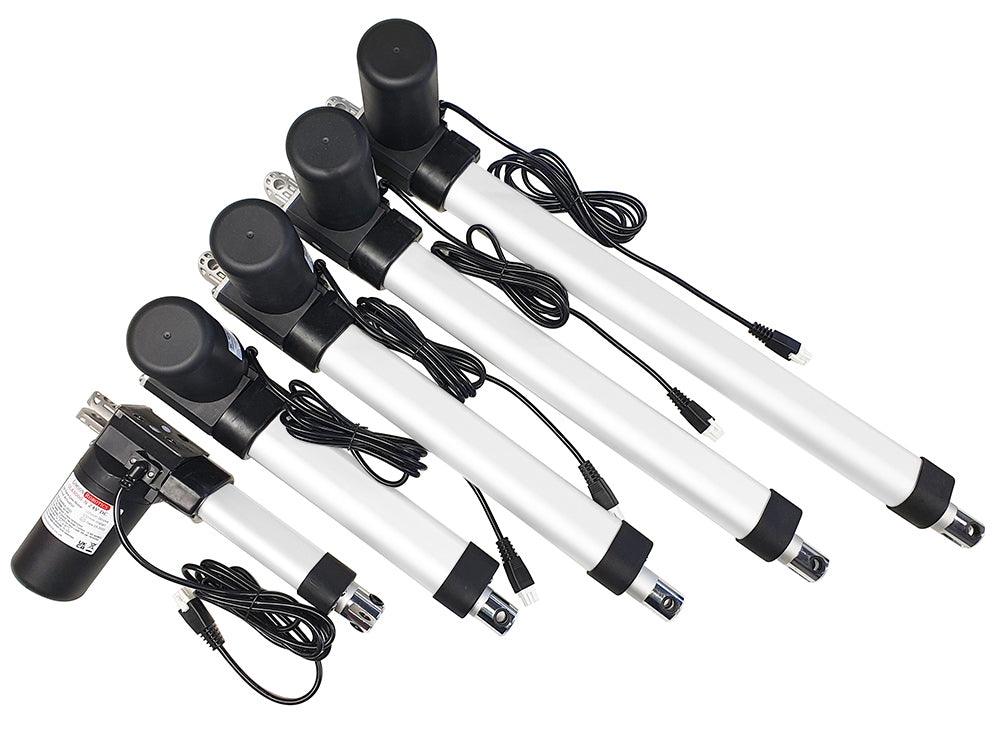
GLA3000-N 24V DC Low-Noise Linear Actuator with Encoder
from £106.50 £124.25 inc VAT
A high strength electric actuator with built-in encoder to allow for position tracking and synchronisation. Often used for adjustable furniture and larger automated assemblies.

Dual Stainless Steel Push Button Mountable Control Handset
£38.00 £44.33 inc VAT
A convenient surface-mountable control box with two stylish spring-return push button switches, a high quality 2m cable, and an interfacing connector included