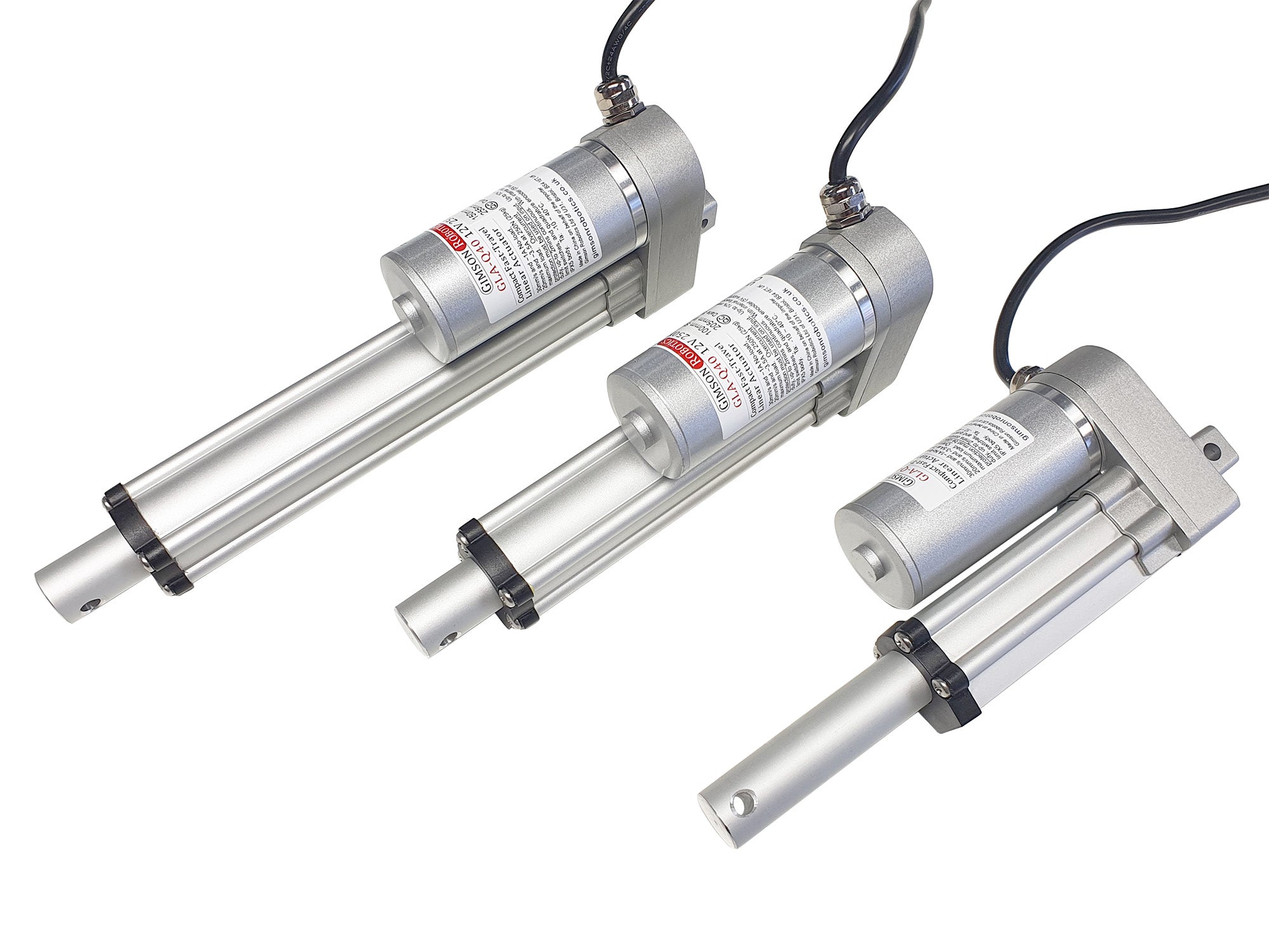
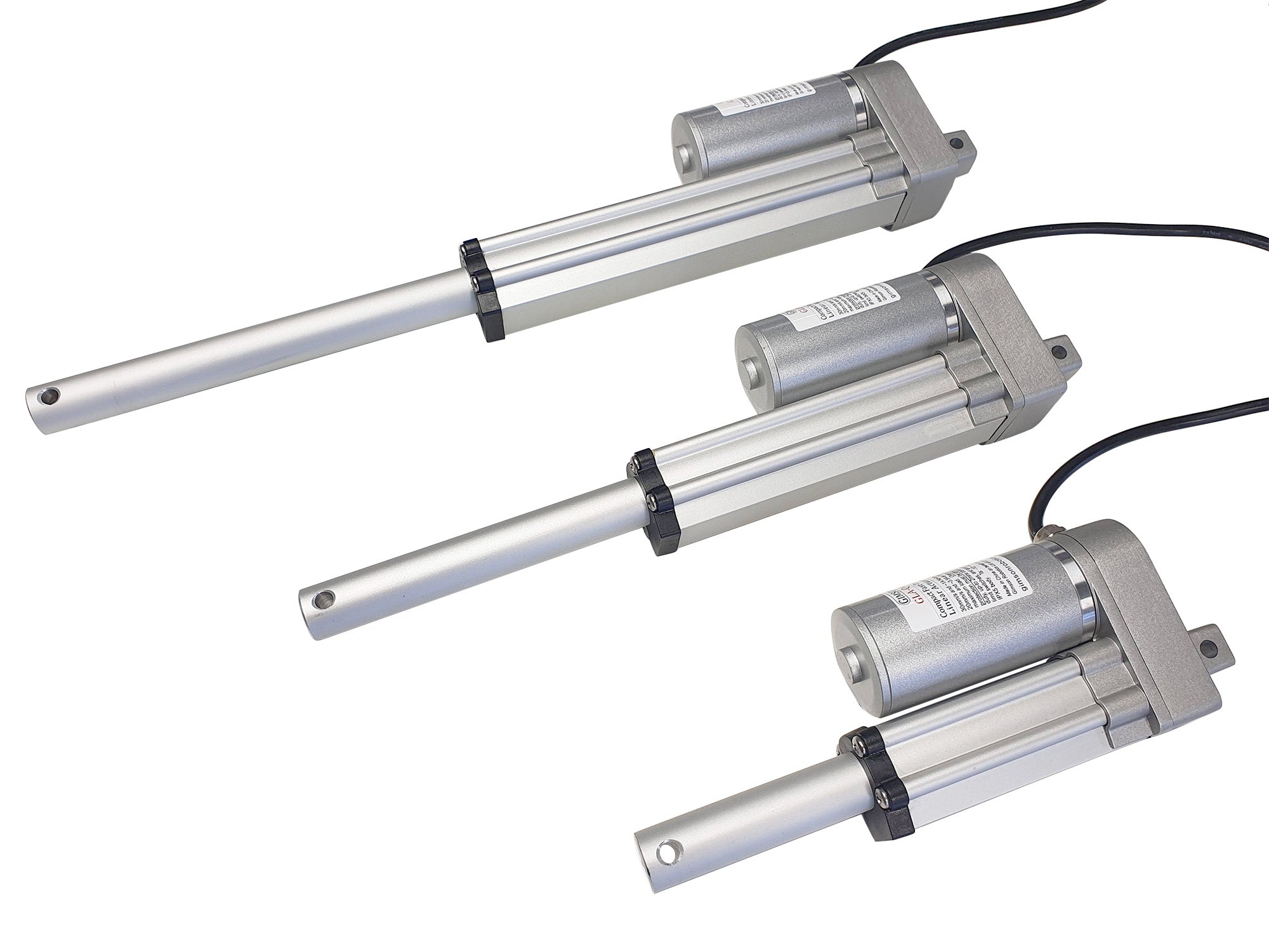
The
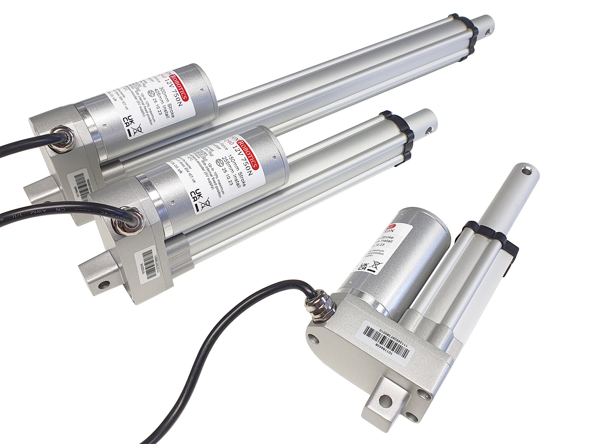
GLA-Q40, a new model for 2023, is one of our more-compact linear actuator options, alongside the
GLA700-2. It is available in a faster-travelling 250N version as detailed on this page, or a slower-travelling but higher force 750N version
which you can find here. T
he two versions of the model share the same outer body, but have different motors and transmissions inside.
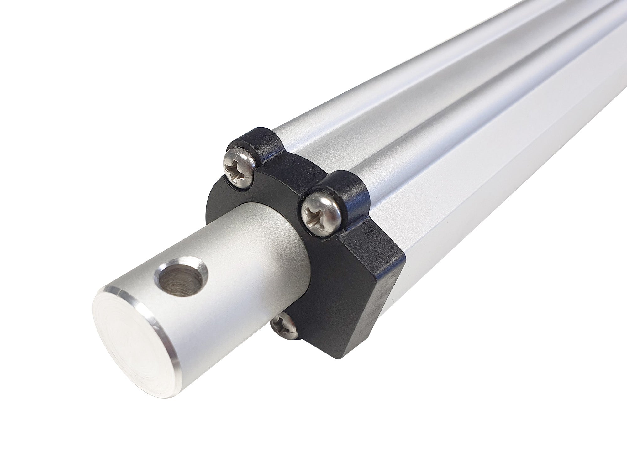
The mounting points at each end of the actuator are 6.5mm in diameter, compatible with both our
zinc-plated steel and
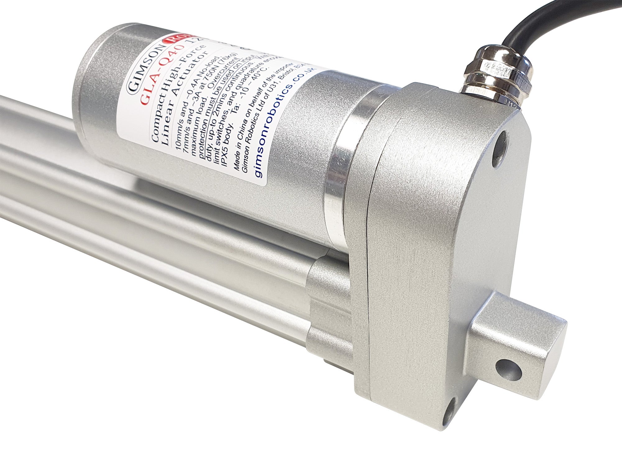
machined aluminium bracket options. The actuator body is of a high construction, quality largely made from strong but lightweight aluminium. Seals and sealant on possible entry points, as well as a metal cable gland, help to provide better protection to dust and occasional splashes than many other actuators on the market, although for harsher operating conditions, including outdoor use, we recommend the similarly-sized
GLA700-2 model, or the larger-sized
GLA1500-N model instead.
As with most of our standard linear actuators this model has built-in limit switches at the ends of travel, meaning that the actuator will stop automatically at the fully retracted and the fully extended positions.
Integrated Encoder, for position detection and synchronisation
This is the smallest of our actuator models to feature a quadrature encoder built-in to the motor. When combined with an appropriate controller (such as our own GR-SYNC) this allows the actuator to have its position and speed tracked, allowing for automated transitions (accelerations and decelerations) and also the possibility of electrically synchronising multiple actuators together. Please contact us if you would like to discuss the control solutions that we can provide.
The encoder does not need to be connected for the actuator to function, and so basic 2-wire operation (only via the Brown and Blue wires inside the 6-core lead) is still possible.
The encoder is powered by two of the six cores of the main cable (+Vcc Red, -GND Black) and is designed to operate fro a 5V supply. It has a dual-channel output (channel A Yellow wire, Channel B Orange wire), with a combined (counting both together) resolution of 10.735 (5sf) pulses per millimetre of travel for the 250N version of the GLA-Q40. As typifies quadrature encoders, one of the channels is out of phase with the other, as such it is possible to tell both the speed (from pulse frequency) and direction (by reading the pulses of one channel and comparing it to the other) of the motor. Given a no-load travel rate of 30mm/s for the 12V motor (when run at 12V) you could expect a pulse frequency across each encoder channel to be around 161Hz at this speed.

Cable & Connections
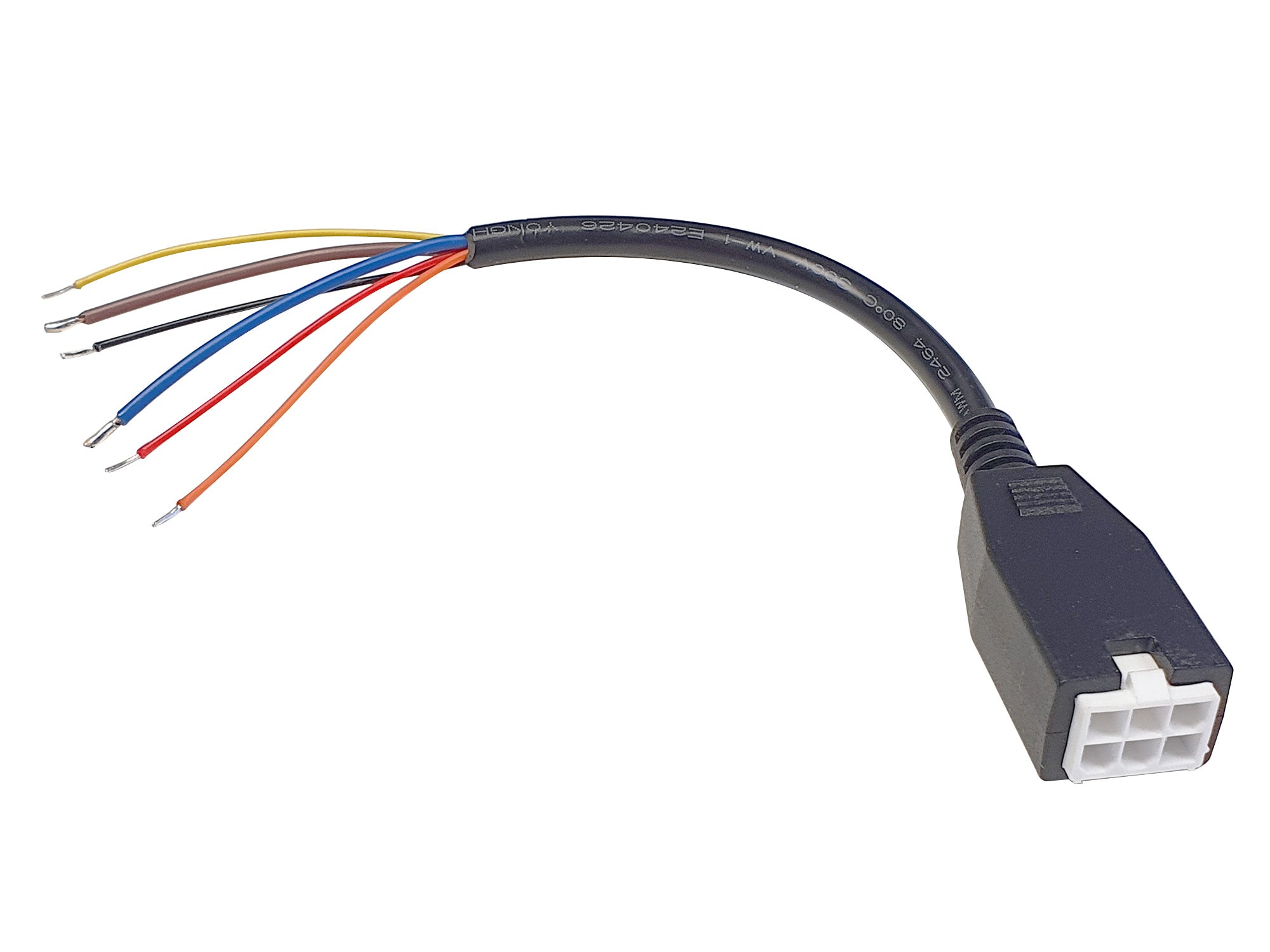
The actuator is supplied with a 2m long PVC-insulated lead as standard, with a Male 6-pin connector (4.2mm pitch, 3x2 format, latched) on the end. The cable has six internal cores: Blue and Brown (to the motor, thicker wires), Red and Black (positive and negative power to the hall sensor encoder circuit, thinner wires), Yellow, and Orange (outputs from the encoder, channel 1 and channel 2, also thinner wires). The connections are illustrated in the below diagram which also shows the limit switch circuit inside each actuator, in series with the brown and blue motor leads.
Please see the Electrical product section for Female 6-pin adapters and extension leads, which are available seperately. If you have a custom lead length or connector requirement, please contact us.
User Advice
As with any brushed DC electric motor, the direction of travel is affected by the polarity of the current supplied to the two motor wires (see leads & connector description above, and on the
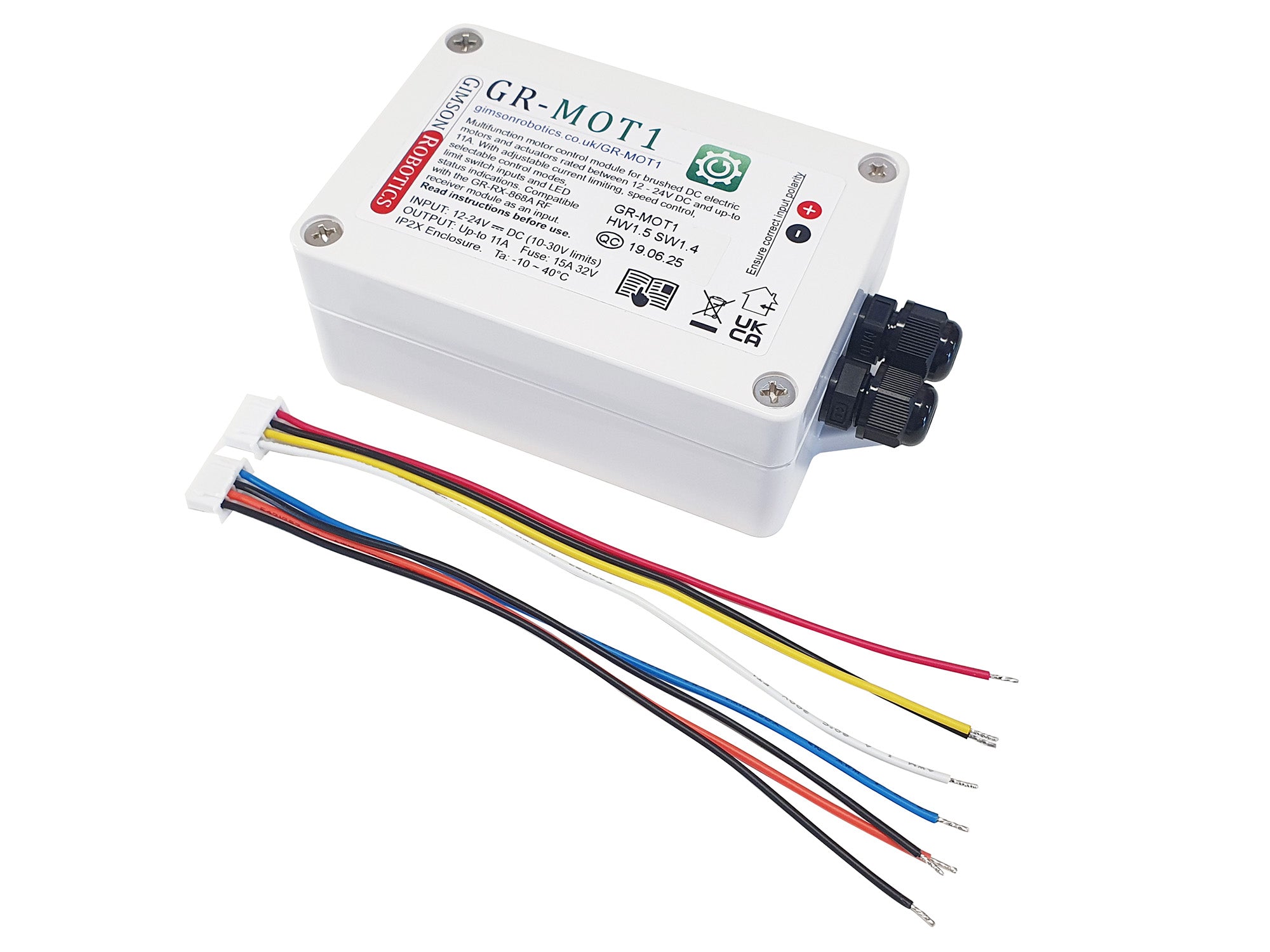
reference sheet, to identify the motor wires). Controlling the direction the current may be achieved using hardware such as a DPDT rocker switch, or a
GR-MOT1 control unit. By varying the input voltage between 0-12V DC it is possible to control the speed of the actuator. Reducing the voltage will also reduce load capacity (for example at 6V the actuator will have roughly half of the maximum load capacity as at 12V, and run with
roughly half the no-load speed). As with any DC motor the actuator may be run at a higher voltage than the nominal 12V DC, however operation at higher voltages
will invalidate the warranty as it creates an increased risk of premature failure (the only exception to this is running with a fully charged 12V battery which may be slightly higher than this, and is allowable provided that sensible overcurrent precautions are in place).
Shock loads through the mounting points should be avoided (shock/impact loads may impart a force greater than the rated load through the actuator).
Be aware of the 'duty cycle' rating of the actuator, which determines the maximum proportion of the time that the actuator should be in operation for, to prevent overheating and ensure longevity. This is specified under 'Operating Characteristics' below.
Ensure that the control hardware and power source are capable of providing sufficient current for the loads you expect the actuator to experience. We cannot be held liable for damage caused to connected hardware due to inappropriate hardware selection.
We recommend, for the GLA-Q40, that active current monitoring and fast overcurrent response are used to protect the actuator against stalling due to an overload, features which are offered by our
GR-MOT1 or GR-SYNC controllers, for example. If the actuator were allowed to stall
without appropriate overcurrent protection then the 250N GLA-Q40 may momentarily draw up to 13A, and could quickly overheat and/or experience permanent transmission damage. Digital current monitoring via a motor controller is able to be much more sensitive, and convenient, than a fuse placed in line with an actuator.
 Device Safety
Electric actuators such as this model are low-voltage electromechanical components that are used in a wide variety of different applications. It is important that the safety of each installation is assessed according to its own requirements, construction, end user and environment. Please see a list of design principles on page 3 of the
actuator reference sheet (PDF), which we strongly recommend that you adhere to in your end-application design.
CAD models (STEP, IGS, Autodesk Fusion 360) of the actuator are available upon request. Contact us with the size(s) and file formats that you require and we'll attach the files in return.
A PDF copy of the actuator datasheet
can be downloaded here.
Operating Characteristics
Motor
12V DC brushed permanent magnet motor, up-to 42W
Speed / Force
30mm/s no-load, reducing to ~20mm/s at the full rated 250N

Operating current
No-load: ~1A
Maximum load: ~3.5A.
Stall current
Up-to 13A. Overcurrent protection must be provided on the input, and this should be configured to limit current to 3.5A or less, to protect the motor and transmission from damage due to overloading.
Maximum load
250N (25kg) for supported (linear) loads. Not designed for off-axis loading.
Maximum duty cycle
10%. This is the maximum proportion of time that the actuator may be in operation for, up to 2 minutes during any continuous stretch. For example, if operating for 1 minute you should then allow it to rest for 9 minutes before operating again, so as to prevent overheating.
Life expectancy
Nominal 60,000 strokes.
Please be aware that there is likely to be some variation in the operating performance from actuator to actuator, you should allow for at least 10% difference above/below the given values when designing for your application. If you intend to use the actuators in sets of two or more driving the same assembly then we would recommend that you use a synchronising motor controller to ensure that the output remains square, even if the load is imbalanced. Please contact us for electrical synchronisation options, or if you have any other questions about specifying an actuator for your project.
Actuator Build Detail
Size
(click on image to expand)
Installation length
This is the distance from the front to rear mounting hole centres
when the actuator is retracted.
| 50mm stroke: 155mm |
100mm stroke: 205mm |
| 150mm stroke: 255mm |
200mm stroke: 305mm |
| 300mm stroke: 405mm |
|
Add the
Installation Length to the
Stroke Length to get the full travel distance, measured between the centre of the two mounting holes.
Mounting
Two 6.5mm-bore holes. One at the end of the cylindrical piston rod, the other towards the rear of the gearbox housing.
Zinc plated steel, and
machined aluminium bracket options are available.
Body material
AL6063-T5 aluminium piston-rod, main sleeve. Cast aluminium gearbox.
Enclosure rated to IPX5, only suitable for outdoor use if protected (fully shielded) from running water and high levels of condensation.
Operating temperature
-10°C ~ +40°C. Please note that current draw can be expected to be higher at temperatures <0°C
Transmission
2-stage gearbox, 1st stage 54:11 helical gears, 2nd stage 41:10 spur gears, total ratio 1107/55:1 (20.127:1 3dp). Low-noise polymer (POM 100P) gears, stress-tested for longevity. 3mm pitch single-start lead screw with POM lead nut.
Limit switches
Two limit switches are installed at the ends of travel which automatically stop travel at the fully retracted and extended travel positions. In the GLA-Q40 these switches are wired, via diodes, to provide motor braking when each limit point is reached. When at a limit, the supply current must be reversed for current to be once again delivered to the motor, allowing the actuator to move away from the limit. See page 3 of the
reference sheet for a circuit diagram.
Cable
2m long 6-core lead (to connector), with 2 x 18AWG cores (Brown and Blue, to motor) plus 4 x 24AWG cores (to quadrature encoder). Male 6-pin connector (5557 type, 2x3, 4.2mm pitch) at end of lead.
Weight
When supplied with standard lead
| 50mm stroke: 840g |
100mm stroke: 930g |
| 150mm stroke: 1020g |
200mm stroke: 1100g |
| 300mm stroke: 1280g |
|
Please contact us if you have any questions about this item, including for bulk pricing information and for application advice.